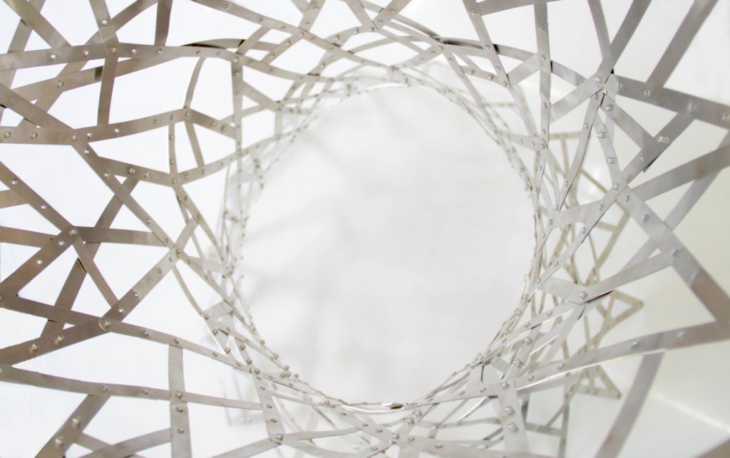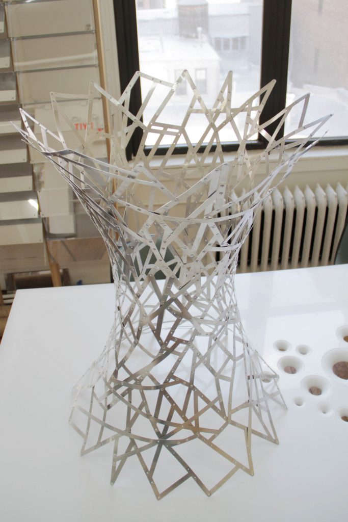
Over the years we have made many form found structures and artworks. When we rationalize the initial surfaces of these projects for production they typically result in a grid shell. This grid is essential in distributing structural loads throughout the surface and gives these minimal surfaces their structural integrity. It is also has a strong aesthetic presence in the work. Over the years we have experimented with subverting the strong rational nature of the grid shell and the digital processes used to produce it (both software and fabrication techniques). This has lead to a series of methods and prototypes to create a thin shell assembly that appears woven and blurs the lines between traditional and digital craft.
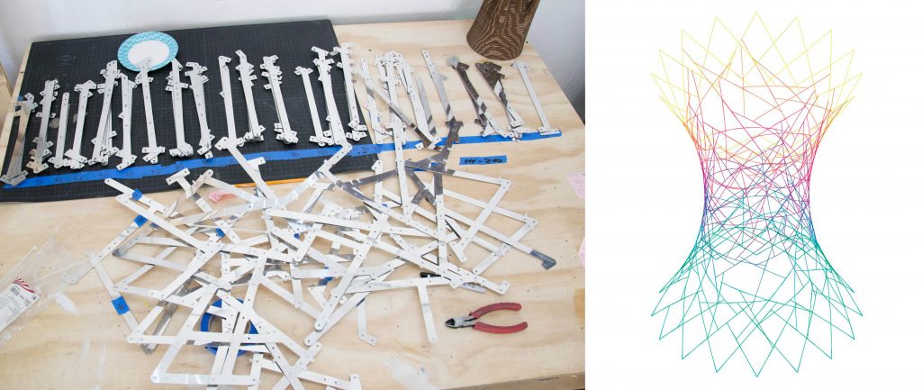
Our initial assumption was that it was simply the form of the surface that gave it it’s structural integrity. With that in mind we simply drew random lines along the surface that connected at their various endpoints. We then generated the profiles and details for these “strips” to be laser cut out of aluminum.
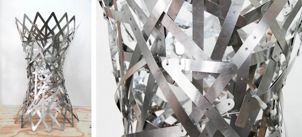
This first prototype did not turnout so well. While the general form was achieved, a lot of the holes did not line up. We didn’t get the general sense that this assembly method helped “find” the shape of the form. With previous projects, the surface began to take shape as we started assembling the pieces. That did not happen in this case.
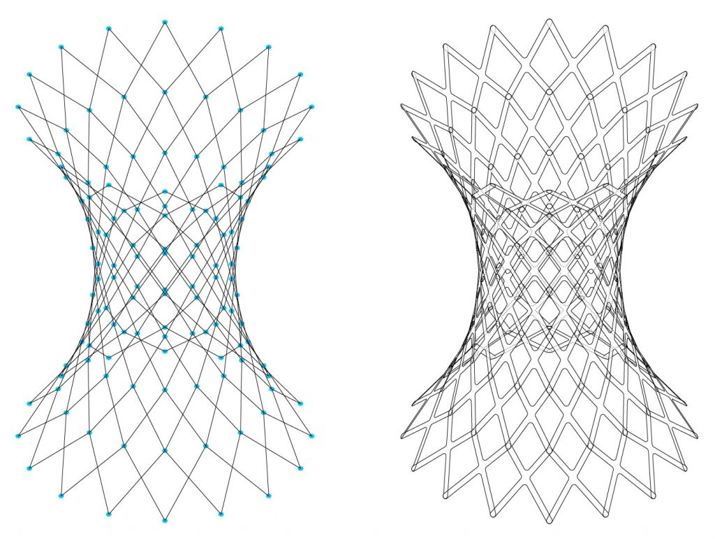
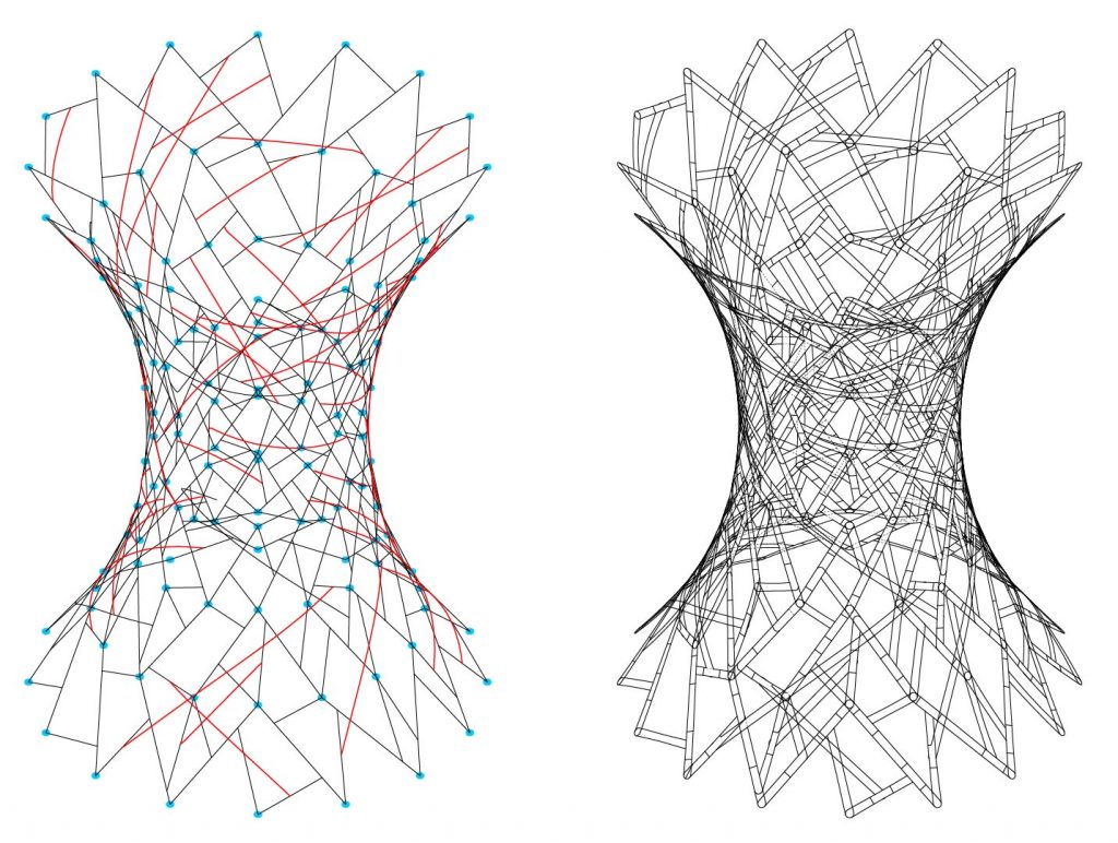
What we thought might be an starlight forward method of randomizing assembly elements, became an interesting problem to solve. We realized our initial assumption that the form was the most important part of these forms being structural stable, was not true. It was both the form and the grid shell, which can be described as a series of faces or network of points.
Typically we create panels or Xs as the assembly units for a complex surface. Versions of those methods can be found here. We started to sketch ideas for an assembly method where we could keep the points of each quad face of a surface intact while randomizing the segments that made that assembly unit. In this case we start with an X as two lines connected points on either corner of the panel. Then we randomize the primary segment and the position f the two secondary segments. The video to the right shows the range of possibilities when a single panel while retaining the vertices of the panel.
The images above show the typical grid shell assembly we have used on the left and the same grid shell to the right with Xs retaining the networks of points, but randomizing the assembly unit segments. Noted in red are a handful of random straps we added that cross panels. These are for the moot part superficial and are added after the panels are assembled.
Download definition for the animation to the right here: Random_X_Panel.zip
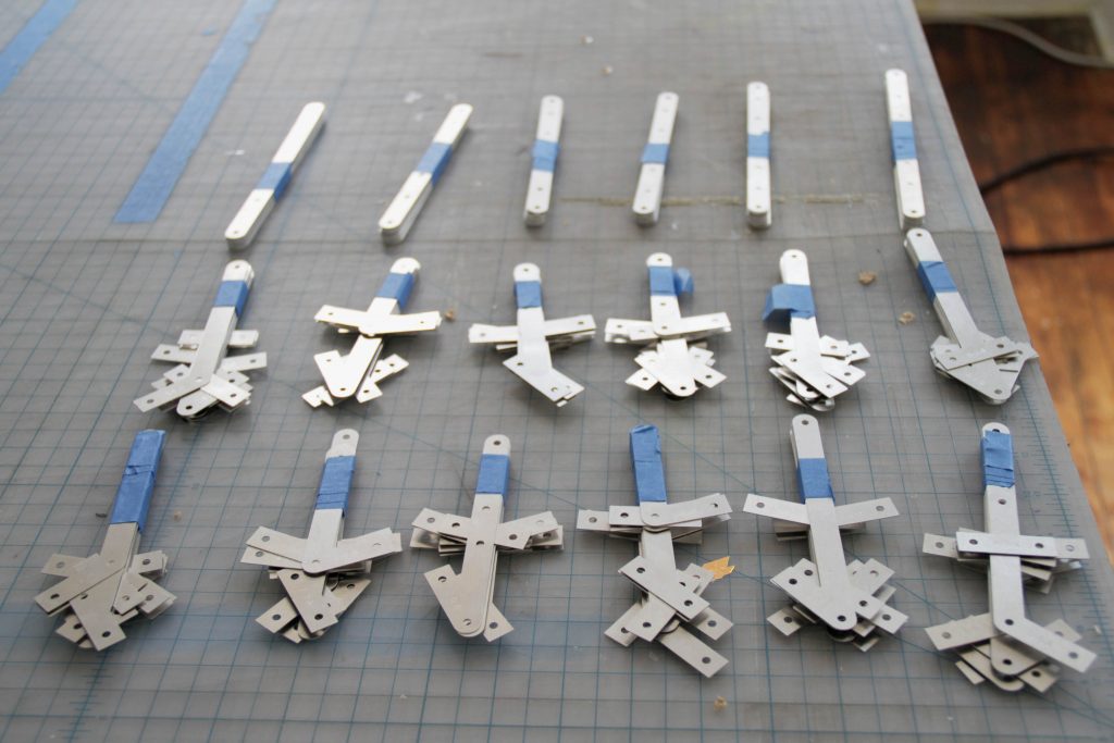
Laser cut aluminum segments of the final prototype organized for assembly.
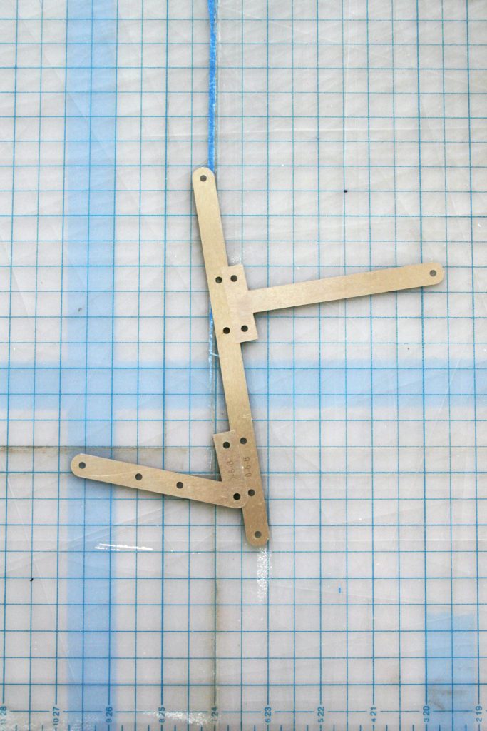
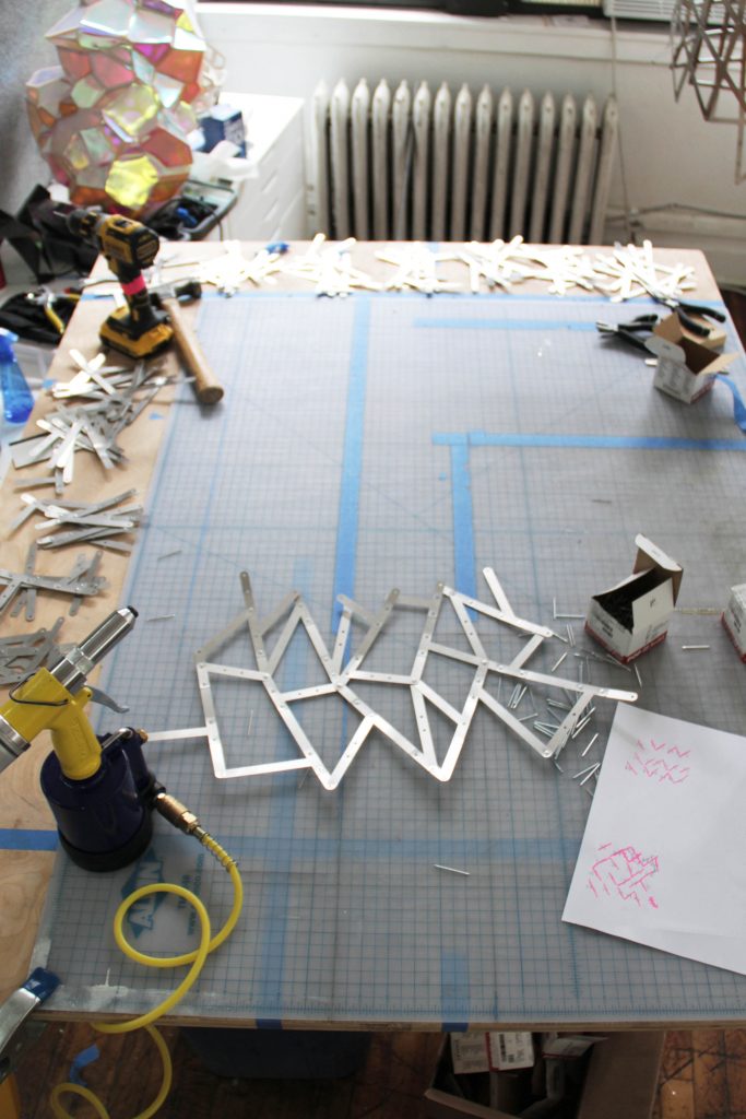
Bocuse these segments are randomized from the panels of the grid shell they can be preassembled into “x” panels, which makes the assembly process much easier than random straps that don’t have an ordering system.
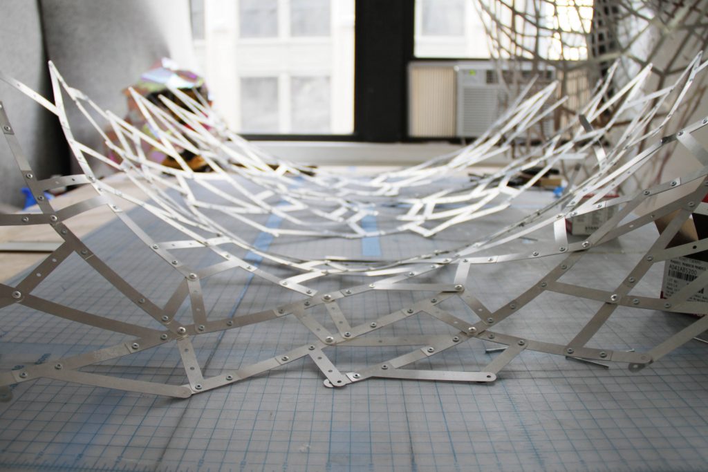
As the prototype was assembled we got the first hint that we were on the right track as the surface started to take on its overall form as each “panel” was added.
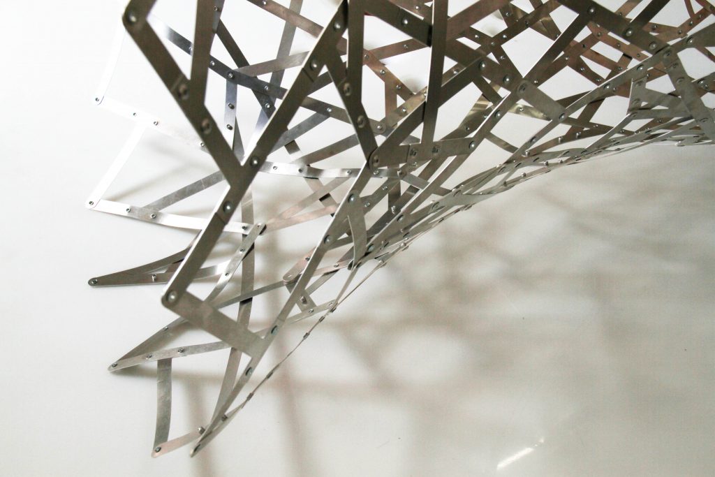
Final prototype showing the woven-like pattern of assembly and the shadows created as light passes through it.
